Our Services
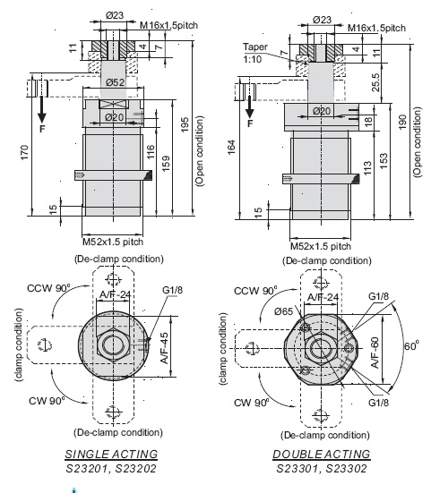
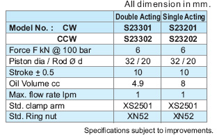
Swing Cylinder Bottom Flange Double Acting
IMPORTANT
- Actual clamping takes place only when the Cylinder has completed its 90o swing stroke.
- Clamping allowed only in clamping stroke not in swing stroke.
- Do not exceed max. flow rate. If flow rates are exceeded, swing cylinder indexing mechanism may be permanently damaged.
DESCRIPTION
These Hydraulic Swing Clamps are must when it is required to keep the fixture work piece area free of straps and clamping components for unrestricted workpiece loading and unloading. These are pull cylinders wherein first part of the stroke is used for turning the plunger 90 right or left. The second part of the stroke is used for Clamping. Single acting swing clamps are spring return type.
NOTE
- Refer General Design notes before selection and use.
- Refer accessories sheet page No. X1 & X2 for clamp arm and ring nut details.
- Given forces are for the standard arm lever. Pressure and flow should be reduced if clamp arm length is increased (Refer Graph sheet No. G1).
- Ordering specification for seal kit.Add prefix "SK" to the model Number.
IMPORTANT
- If the system flow rate exceeds, use one way flow control valve in the upstream hydraulic lines.
- Length of Clamping arm, weight of Clamping arm, max. Permissible flow rate and working pressure are all important. Refer graphs for arm length and working pressure.
- Keep weight of Clamping arm to a minimum.
FEATURES
- Min / Max, Operating Pressure 40/100 bar.
- Large clamping range.
- Single & Double acting ranges.
- Very compact cylinder design.
- 360o adjustable arm location.
- No stroke during swing action.
- Can be threaded directly into a fixture/ring nuts can be used.
98111-82148