Our Services
High Vacuum Transformer Oil Filtration And Dehydration Plants
High-Vacuum Transformer Oil Filtration And Dehydration Plants are suitable for all types of electrical insulating oils. We have standard high-vacuum filtration and dehydration plants to remove moisture (free as well as dissolved), gases, dirt and oxidation products from mineral-based and synthetic, silicon oils and others. Systems are in flow rates from 300 LPH to 12000 LPH. Custom built plants can be provided as per customer’s specific requirement, such as more flow-rates. These plants work on low temperature, high vacuum principle. Plants mainly consist of heating, filtration and vacuum system. Heating system aids to the filtration and moisture removal. Filtration systems remove suspended particles down to 1 micron such as rust, dirt, scales, colloidal carbon etc. Vacuum Systems remove moisture (emulsified as well as dissolved) down to < 5 – 10 ppm depending on the working vacuum of the plant.
Transformer / Insulating Oil Filtration and Dehydration Plants / Purifiers are available for:
1. Transformer and capacitor manufacturers –skid mounted plants for preparation of new oils prior to apparatus filling and impregnation.
2. Transformer repairers -complete plants for preparation of new oils and regeneration of used oils for reuse. We can provide the purification system you need as well as vacuum storage tanks and transformer filling and emptying / pumping station.
3. Transformer owners -portable plants are available in a variety of trailer-types and sizes to allow on-site servicing of transformer oil right in the substation. Trailers are available with a wide variety of options including laboratory space, oil-testing equipment. Plants are designed for drying out of the transformer insulation and oil filling and impregnation under vacuum. Hot oil circulation and hot oil spray methods can also be used.
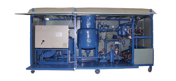
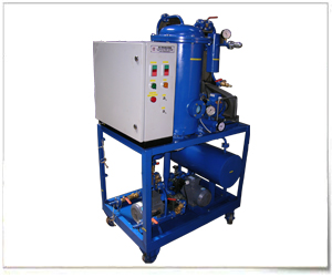
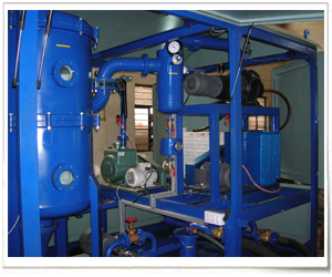
Plants are available in different types of constructions such as open & enclosed models, stationery, portable & mobile models, with single & double stage degassing / dehydration system.
Our single stage plants (Models 1V) are capable of attaining following oil parameter in 3-5 passes and Two Stage Plants (Models 2V) in 1-3 passes depending on the oil condition:
|
SR. NO.
|
PARAMETERS
|
UNITS
|
BEFORE FILTRATION
|
AFTER FILTRATION
|
|
1 |
Break Down Voltage with 2.5mm Electrode Gap. |
kV |
25 |
>50- 70 |
|
2 |
Moisture Removal |
ppm |
50-100 |
Up to < 5 - 10 |
|
3 |
Neutralization Value (With IRC Option Only) |
mg of KOH/g |
0.5 |
< 0.1 |
|
4 |
Particle size (Filter Fineness) |
Micron |
Visible |
< 1 |
|
5 |
Gas Content |
% Vol./Vol. |
<10% |
< 0.1% |
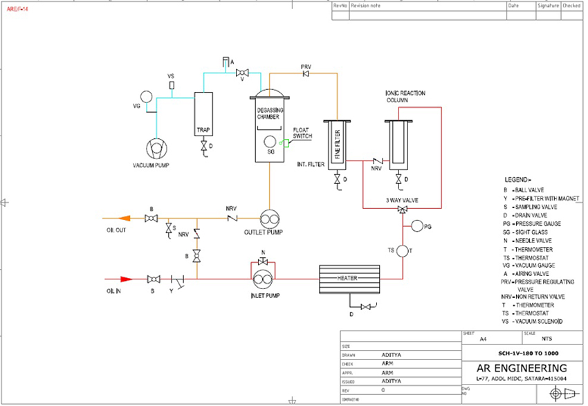
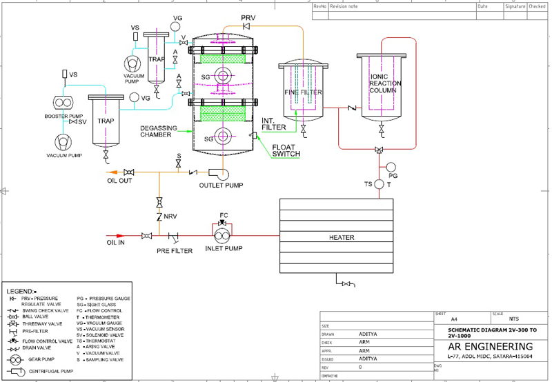
Generally, the plants are as per the schematic diagram attached. The plants mainly consist of the following major components:
Working Systems
1. OIL TRANSFER & CIRCULATING SYSTEM : It mainly consists of Inlet Pump (Gear type positive displacement), Outlet Pump (Positive displacement Gear type or Glandless Centrifugal) and necessary valves & piping as per the schematic diagram to ensure easy operation and maintenance. Complete system is vacuum tight to have a leak-proof operation. The piping joints are flanged type with O’rings. Chambers are provided with suitable draining arrangement.
2. HEATING SYSTEM :
- It is capable of heating the oil from 25°C to 80°C. It contains Insulated heat exchanger with indirect low watt density (Less than 2W/cm2) bobbin type electric heaters. Oil temperature is controlled with thermostat. Suitable oil distribution system is provided to ensure uniform flow of oil over heaters. It will be provided with:
- Indirect Type Heating Elements made out of Nichrome wire elements fixed in refractory formers and inserted in finned MS tubes welded to heater chamber plate. Watt Density will be less than 2 Watts / cm2.
- Temperature Control: Thermostatic
- Temperature Indication: Dial Stem Type Thermometer.
- Thermal Insulation: Glass Wool enclosed with CRCA sheets.
3. FILTRATION SYSTEM :
It is suitable for removing suspended particles such as colloidal carbon, oxidation sludge, dirt, rust, up to < 1 micron. It consists of PRE FILTER, INTERMEDIATE FILTER and FINE FILTER elements
- PRE FILTER: is a metallic strainer with magnet. It removes magnetic and coarse suspended particles and to protect inlet pump from damage due to abrasion.
- FINE FILTER: removes all suspended particles up to < 1 micron. Filter Elements are either non-hygroscopic molded cellulose cartridges or cleanable (with reverse airflow) edge type filter candles. Filter cartridges are easily replaceable. Additional Intermediate filter is provided to increase life of fine filter elements.
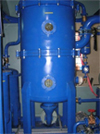
4. DEGASSING & DEHYDRATION CHAMBER :
It is designed to remove large portion of dissolved impurities (Including Moisture) from oil. Knitmesh packing trays and oil dispersing system are provided to have sufficient exposure of oil to vacuum during filtration. Oil level is controlled with float switch. It will be provided with:
- Shower arrangement and Raschig ring trays for formation of thin oil film to get more exposure of oil to vacuum.
- Siphon seal to ensure longer travel of oil during degassing (for 2V plants)
- Sight glasses, illuminating lamps and float switch to control oil level.
- PRV before degassing chamber & SCV after Outlet Pump will be provided to avoid flooding of degassing chamber in case of power failure.
5. VACUUM SYSTEM :
It will consist of following components:
FOR FIRST STAGE OF DEGASSING:
VACUUM PUMP: Rotary Oil Sealed Pump with following specifications:
- Free air displacement -*** LPM.
- Make - M/s Indo-Woo sung or similar
- Electric Motor – ** H.P. Foot Mounted,
- Working Vacuum - < 5 torr, Ultimate vacuum - < 0.005 torr
FOR SECOND STAGE OF DEGASSING (ONLY FOR 2V PLANTS):
ROOTS PUMP: FREE AIR DISPLACEMENT: *** M³/Hr
- Make – M/s Everest or similar
- Electric Motor – ** H.P. Flange Mounted
VACUUM PUMP:Rotary Oil Sealed Pump with following specifications:
- Free air displacement - *** LPM.
- Make - M/s Indo-Woo sung or similar
- Electric Motor – ** H.P. Foot Mounted,
- Working Vacuum - 0.1 torr, Ultimate vacuum - 0.001torr
6.GAUGES AND INSTRUMENTS :
The plant will be provided with following gauges and instruments for easy operation and control of it.
- Pressure Gauge: 0 – 7 Kgf / cm², Glycerin filled Bourdon Dial type Ø 63 / 100 mm, M/s Shreeji or similar make.
- Thermometer: 0-150°C, Dial stem type. Ø 63 / 100 * 150 mm stem Length, M/s Shreeji or similar make.
- Thermostat: 30-110°C, Capillary type. Sai-Ego or similar make.
- Float Switch: Float operated magnetic reed switch, RS Model, M/s Sukrut make.
- Vacuum Gauge: 0 – 760 mm of Hg Bourdon Dial Type Ø 63 / 100 mm, M/s Shreeji or similar make
- Digital Vacuum Gauge – Ace Instruments make.(Only for 2V plants)
7. VALVES AND PIPING :
The plant will have necessary valves and piping for easy operation and maintenance of the plant as follows:
- Oil Valves: ** NB Ball type valves with seals suitable for under vacuum operation. Itap Italy, R / N USA or similar make.
- Drain Valves: 15 & ** NB Ball type valves with seals suitable for under vacuum operation. Itap Italy, R / N USA or similar make.
- Airing Valve: Quick Release types 10 NB, AR Engineering Make. Solenoid valve (for 2V plants).
- Flow Control Valve: Needle or Piston type, AR Engineering Make.
- Vacuum Valve: ** NB Ball type valves with seals suitable for under vacuum operation. Itap Italy, R / N USA or similar make.
- Swing Check Valves – ** NB Ball type valves with seals suitable for under vacuum operation. Itap Italy, R / N USA or similar make.
- PRV - ** NB Ball type valves with seals suitable for under vacuum operation. Itap Italy, R / N USA or similar make.
- Pipe Connections: Flange type with synthetic rubber O-ring. AR Engineering Make
- Inlet and Outlet Hoses: ** NB Synthetic Rubber reinforced or nylon braided with quick coupling.
8. CONTROL PANEL :
The plant will have centralized control panel for easy and safe operation of the plant. It will have necessary Electrical Control Contactors, Pilot lamps, push buttons, back-up fuses, connectors strips, MCB, Isolator switch etc. All material used in the plant will be of Reputed Make such as GE, English Electric, Siemens, MDS, Anchor, Kaycee, Datar, etc. The plant will have following inter locks:
- Inlet Pump – Heaters: Heaters will not be ON unless inlet pump is ON.
- Float Switch – Inlet Pump: Inlet Pump will be off when oil level rises.
- Thermostat – Heaters: Heaters will be off when temperature rises.
- Booster pump – Vacuum gauge relay – Booster is ON only when vacuum is < 50 torr ( Only for 2V plants )
Optionals:
IONIC REACTION COLUMN : It will be fabricated out of MS sheets, plates. It will contain sufficient quantity of activated alumina (** Kgs) for reduction of acidity level of oil to less than 0.05 mg of KOH / gm oil. It will be provided with, By-pass arrangement when not necessary & Alumina Cage (fabricated with CRCA caps & SS wire mesh) for easy replacement. It is fitted on the plants of flow rate > 2400 LPH as a standard fitting and bypass arrangement.
TRANSFORMER EVACUATION SYSTEM : It will be suitable for working vacuum of either 5 – 10 torr or 0.1 – 0.5 torr. It will be provided with Rotary Oil Sealed Pump or Roots Rotary combination along with Moisture Traps (water cooled) with drain, airing valve, NRV, Vacuum Gauge will be provided as per the schematic diagram.
Plant Can Be Supplied With Followings :
- BDV TESTING KIT
- ON LINE MOISTURE MEASUREMENT KIT
- ACIDITY TESTING KIT
- FLOW METER
Points For Selection Of Plants :
- RANGE OF SIZES OF TRANSFORMERS : FLOW RATE IS DECIDED
- LOCATION OF TRANSFORMERS TO BE FILTERED: MOUNTING & CONSTRUCTION TYPE IS DECIDED.
- REQUIREMENT OF OIL QUALITY & TIME AVAILABLE FOR FILTRATION & DRYING: WORKING VACUUM IS DECIDED
- WORKING VACUUM: SINGLE OR TWO STAGE DEGASSING IS DECIDED
How To Configure The Model :
|
||||||||||||||||||||||||||||||
|
||||||||||||||||||||||||||||||
|
|
||||||||||||||||||||||||||||||
|
OPEN STATIONERY MODEL- Suitable for indoor fixed place operation. |
||||||||||||||||||||||||||||||
.jpg)
.jpg)
.jpg)
.jpg)
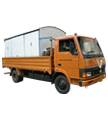

- ENCLOSED STATIONERY MODEL - Suitable for permanent mounting on vehicle.
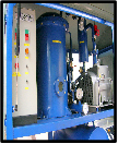
- OPEN PORTABLE MODEL – Suitable for indoor movable operation. Small plants are suitable for carrying in the vehicle for on-site operation.
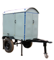
- ENCLOSED MOBILE – Suitable for towing with the vehicle and on-site operation.
|
||||||||||||||||||||||||||||||||||||||||||||||||||||||||||||||||||||||||||||||||||||||||||||||||||||||||||||||||||||||||||||||||||||||||||||||||||||||||||||||||||||||||||||||||||||||||||||||||||||||||||||||
|
|
|
|||||||||||||||||||||||||||||||||||||||||||||||||||||||||||||||||||||||||||||||||||||||||||||||||||||||||||||||||||||||||||||||||||||||||||||||||||||||||||||||||||||||||||||||||||||||||||||||||||||||||||||
|
||||||||||||||||||||||||||||||||||||||||||||||||||||||||||||||||||||||||||||||||||||||||||||||||||||||||||||||||||||||||||||||||||||||||||||||||||||||||||||||||||||||||||||||||||||||||||||||||||||||||||||||
|
|
|
|||||||||||||||||||||||||||||||||||||||||||||||||||||||||||||||||||||||||||||||||||||||||||||||||||||||||||||||||||||||||||||||||||||||||||||||||||||||||||||||||||||||||||||||||||||||||||||||||||||||||||||
98111-82148